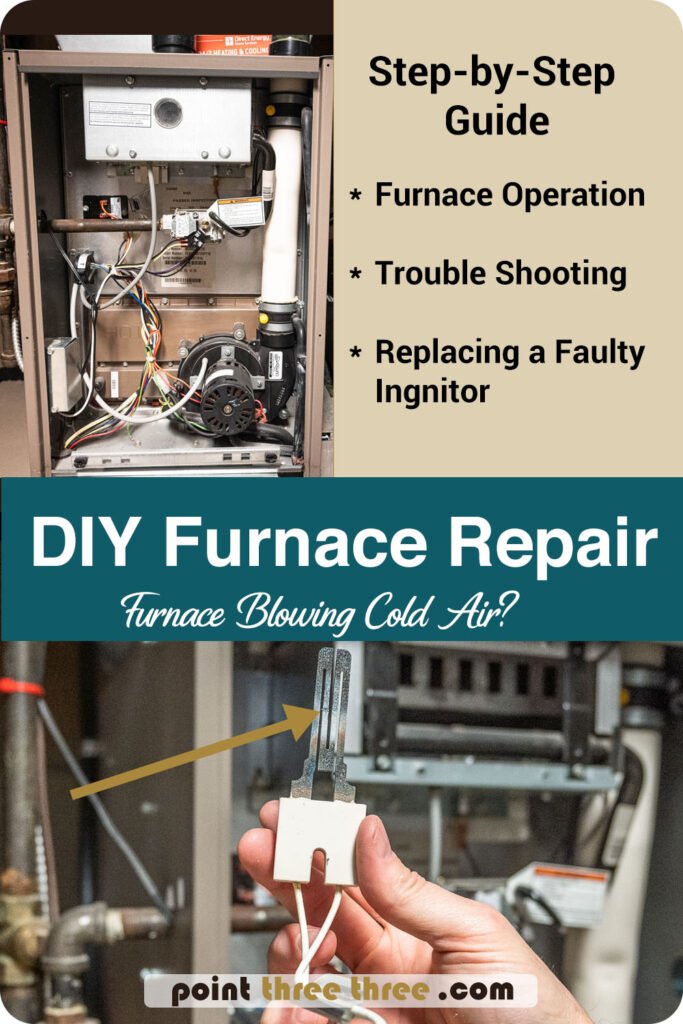
Is your Furnace Blowing Cold Air?
It’s the dead of winter, and its freezing outside. Is your Furnace Blowing Cold Air? It’s the absolute worse timing for your furnace to fail. Desperate texts to your HVAC technician go unanswered, and after just one night, you feel the cold creeping into your bones, turning your cozy home into an unexpected arctic adventure. If you are reading this blog, I’m guessing it sounds familiar?
You have a couple choices now, either start calling a bunch of Furnace Repair services, OR, put on your DIY hat and try to troubleshoot and fix it yourself.
A couple of weeks ago, when it was a bone-chilling -15°C outside, I found myself in this exact predicament. With no immediate help available, armed with my digital multimeter and tool bag, I embarked on a DIY furnace repair journey.
Trouble shooting a faulty Furnace Ignitor
Check the basics first:
-
- Check the thermostat, is it on heat and no issues?
-
- Check the air filter, is it clean?
-
- Is the blower motor on?
-
- Is there a pilot lot, or any flame on the burner?
-
- Are there any codes being flashed from the control board?
-
- Is the furnace Power Switch ON?
If nothing is readily obvious, its important to understand the basic sequence of operation of your furnace. If you understand that, you can then further troubleshoot what might be the root case.
Furnace Sequence of Operation
Basic Sequence of Operation:
- Call for Heat : The thermostat reaches a set temperature, or is turned up by the homeowner and sends a signal for the furnace to turn on.
- Furnace Main Circuit Board Check : The thermostat provides a voltage to the W terminal on the control board.
- Inducer Motor Starts : The control board powers the draft inducer to start it. The inducer motor begins to spin and creates a vacuum to ensure the leftover gasses go out the exhaust pipe.
- Pressure Switch Closes : If the inducer is running, it should then close the pressure switch and circuit.
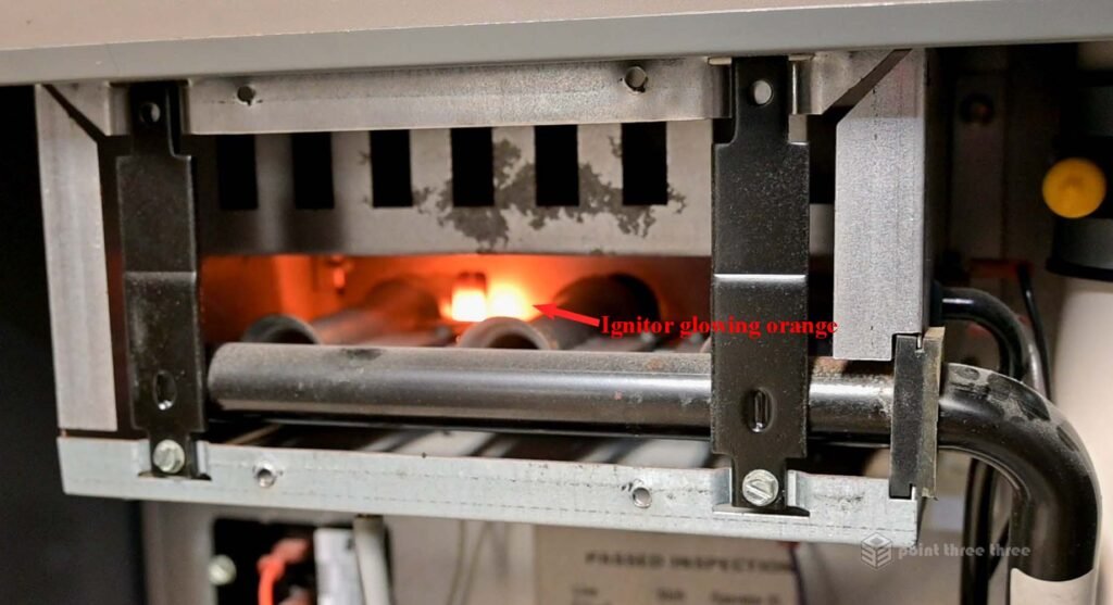
- Furnace Ignitor Powers on : The control board sends power to the furnace ignitor which should glow bright orange for a couple of seconds.
- Gas Valve Opens – Combustion : The gas valve will open allowing gas to flow through the venturi tube where it is combined with air to ensure proper combustion.
- Flame Sensor Senses Ignition : The flame sensor will sense ignition and turn the ignition source off. If the gas burners do not ignite for several seconds the flame sensor does not sense the flame and the control board turns the gas valve off.
- Blower Motor Starts : After a set time, the blower motor will start, blowing air over the system’s heat exchangers to provide heat to the home.

Diagnostic Fault Codes
In my circumstance, the furnace was not blowing any warm air.
Everything on the “basic” list above checked out except for a flashing red code. There is a small site window on the front of the furnace that you can look through that will show you a section of the Furnace control board and an LED indicating status. In normal operation the LED should be a constant green. In my case, it was blinking red 7 times.

So how do you know what this code means? Most furnaces will have a schematic and diagnostic fault code stickers adhered to the backside of the panels.
Before you start, turn the power off to the furnace. In my case its wired to switch in the rafter but in many cases the switch will be right beside and or attached to the furnace.

Remove the 4 thumb screws on the panel. Your furnace may not have these. Typically the panel would then slide up an inch and you pop it out. In my case, I of course needed to remove the top panel first.

The 7 red flashes fault code in my instance = “Ignition lockout due to retries”. I was not positive what this meant but likely got me to focus on the Ignitor and that portion of the sequence.
Furnace Components

Components labeled in above image:
- Power Source (120V AC)
- Induction Motor
- Pressure Switch
- Limit Switch
- Ignitor
- Burner
- Exhaust Vent Pipe
Now that I had the furnace open, I wanted to better observe what was happening during a call for heat so that I could further troubleshoot.
So that you can operate the furnace with the panel off, you will need to close the Panel Door Switch. Simply put a piece of duct tape over the switch. Then turn on the Furnace Power Switch. Observe the sequence of operations.

Parts labelled above:
- Furnace Control Board
- Panel Cover Switch (If switch is open, power is cut off. When panel is on, it physically closes it. Hence the tape so we can test the operation with the panel off)
- Control board LED
Testing and Observations
Here is what I observed:
-
- Control board came on with a Green LED
-
- Induction Motor Turned On
-
- I heard a “click” from the Pressure Switch. As least I thought I did.
-
- NOTE: The Pressure Switch “circuit” was the root cause for my furnace not blowing warm air 2 years earlier. In that case the root cause was “gunk” built up in the tubes which connect the switch to the Induction motor, preventing the switches physical diaphragm on the inside from “closing”.
-
- I looked through the site glass of the burner and did NOT see the Ignitor Glow and hence no flames.
-
- After some time, the control board would start displaying the fault code.

Therefore, I assume that I have an some issue which is causing the Ignitor to NOT turn on.
If you have a Digital Multimeter, this is where it will come in handy to pin point test the next step.
There are two checks you can perform to check the ignitor.
-
- The Ignitor is supplied with 120V ac. If the Ignitor is NOT receiving 120V, then its likely an issue upstream in that circuit that is faulty. If it is getting 120V and not turning on/glowing, its likely the Ignitor.
-
- Next you can check the resistance across the Ignitor. It should read less than approximately 100 ohms across the terminals. If it is Open Circuit, then you confirmed you have a faulty Ignitor and needs to be replaced.
First turn the power off until you are ready to do your pinpoint tests.
Unplug the connector going to your Ignitor.


In my case, I did measure 120V AC from the source side of the connector. So we had power going to the Ignitor.

The resistance check measured my Ignitor as Open Circuit.
Therefore I have confirmed my Ignitor is faulty and needs to be replaced!
Removing the Ignitor
To remove the Ignitor, its simply the one screw that you see in the image above and it should just slide out.

Purchasing a Replacement Ignitor
My Ignitor had a label fixed to the wire with a part number on it. I was able to find a compatible Furnace Ignitor replacement on Amazon for ~$40. However, when the part arrived it had the wrong connector! It came with the Male end and I needed the female connector as you can see in the photo. In the end, I got a replacement part at a local HVAC supplier which had the correct female side. So check the details when you order your part!
After plugging everything back together, I left it open for the first run, in order to view whether all was functioning properly as depicted in the images below.

Additional Resources
Some additional resources that can improve your furnace knowledge:
Of course there are also many Youtube videos as well that you can reference.
With patience, the right tools, and a bit of DIY spirit, you can tackle furnace issues on your own and restore warmth to your home.
Good luck and hopefully this helped!
Disclaimer : I am not a licensed HVAC technician nor claiming to provide expert advise on your furnace. You have to use your own common sense when tackling a project like this.
If you are interested in some other DIY projects check out my DIY Everything Blog.